
 Juraj Ďuďák
1b21f45e6e
rely on circular UART RX FIFO buffer in app
Juraj Ďuďák
1b21f45e6e
rely on circular UART RX FIFO buffer in app
|
2 months ago | |
|---|---|---|
| assets | 2 years ago | |
| include | 2 months ago | |
| src | 2 months ago | |
| .clang-format | 2 years ago | |
| .gitignore | 2 years ago | |
| .gitlab-ci.yml | 2 years ago | |
| Doxyfile | 2 years ago | |
| Makefile | 2 years ago | |
| README.md | 1 year ago |
README.md
nano Bus
Protocol stack for Body Area Network Modules. The nBus protocol is an application layer protocol for connecting sensor nodes to a higher-level control unit in the BAN. The main development goal is to provide a reliable and secure way for real-time monitoring and feedback of health parameters during clinical or home rehabilitation and physiotherapy.
How to integrate to project
The basic control structure is nBusPlatformInterface_t. You have to define basic functions whtch will be interact with protocol stack
typedef  struct{
void (*uart_receive)(uint8_t *data, int n);  // Start reciving n bytes and store in to data array.
                                             // In interrupt mode.
void (*uart_transmit)(uint8_t *data, int n); // Send n bytes stored n data array
void (*led_on)(void);                        // turn on signaliation LED
void (*led_off)(void);                       // turn off signaliation LED
void (*led_toggle)(void);                    // toggle signaliation LED
void (*delay_ms)(uint8_t);                   // blocking delay in ms
uint8_t (*loop_callback)(void);              // application calback for processign events: RX_complete, sensor_data_ready
}nBusPlatformInterface_t;
Communication timer configuration: @deprecated
- Timer used in
timer_uart_startfunction have to be preconfigured to time period equivalent to time needed to receive 1 byte. This time depend on selected communication speed of UART interface. - Timer have to tun in interrupt mode.
In application, the 2 more callback have to be defined:
- UART Complete Receive Callback - when requested data are received.
TIMER Period Elapsed - when timer period is elapsed These 2 calback have to be imeplement as follows:
static  inline  void  nbus_app_UART_RX(){
nbus_cb_UART_RX();  // call function in nBus stack
}

static  inline  void  nbus_app_TIM_periodElapsed(){
nbus_cb_TIM_periodElapsed(); // call function in nBus stack
}
Practical integration
Include file
Copy file nbus_config.h.default to your project and rename it to nbus_config.h
These are important configuration settings:
- MODULE_ADDRESS - address of module. Allowed values are from 1 to 31
- MODULE_MASTER - Master module functionality. Allowed values are 0,1.
- MODULE_SLAVE - Slave module functionality. Allowed values are 0,1.
- MODULE_NAME - name of developed module. Max 8 chars.
- MODULE - type of slave module. Use of these constat
- MODULE_DUMMY
- MODULE_FSR
- MODULE_IMU
- MODULE_GNOSTIC_DISTANCE
- UART_BAUDRATE - Uart baudrate. This communication speed have to be set in your application
Include following header file to project:
#include "nbus_app.h"
Create platform driver
nBusPlatformInterface_t hw_platform ={
    uart_receive,  // these are pointers to existing functions
    uart_send,
    led_on,
    led_off,
    led_toggle,
    delay_ms,
    loop_callback
};
Initialise and start application
nbus_init(getDummyDriver(), &hw_platform);
nbus_init_app(NULL, NULL);
where getDummyDriver() return pointer to structure nBusAppInterface_t, which implement specific sensors.
Every sensors/device have to implement the basic functions:
typedef  struct{
    void (*init)(void *hw_interface, void *hw_config);
    void (*reset)();
    nBus_sensorType_t(*getType)(uint8_t sensor_index);
    uint8_t (*getSensorCount)();
    uint8_t (*getData)(uint8_t sensor_index, uint8_t *data);
    uint8_t (*setData)(uint8_t *data);
    uint8_t (*hasParam)(uint8_t sensor_index, nBus_param_t param_name);
    uint8_t (*getParam)(uint8_t sensor_index, nBus_param_t param_name);
    nBus_param_t (*setParam)(uint8_t sensor_index, nBus_param_t param_name, uint8_t param_value);
    void (*start)();
    void (*stop)();
}nBusAppInterface_t;
Provide EEPROM configuration memory interface
nBus_MemoryDriver memory_ec20 = {
    DS28EC20_init,
    DS28EC20_readData4B,
    DS28EC20_readData2B,
    DS28EC20_readData1B,
    DS28EC20_writeData,
    DS28EC20_getId,
    DS28EC20_getCapacity,
};
memory_ec20.init(ONE_WIRE_GPIO_Port, ONE_WIRE_Pin);  //applicatin level function call
nbus_init_memory_driver(&memory_ec20);  // pass memory driver to nBus
Note: if no memory used, initlialize it as memory dummy driver.
#include "memory_dummy.h"
nbus_init_memory_driver(getDummyMemDriver());  // pass dummy memory driver to nBus
Run application stack
The function nbus_stack() contains of application loop.
nbus_stack();
nBus interface
nBus interface is pointer to structure nBusAppInterface_t. It contains these functions:
void init(void *hw_interface, void *hw_config);- Configure hardwre module/sensor.
hw_interfacecan represent communication bus orNULL. hw_configcan store configuration data for module orNULL.
- Configure hardwre module/sensor.
void reset();- reset connected device/sensor. Can be empty.
nBus_sensorType_t getType(uint8_t sensor_index);- return type of sensor connected to module. The
sensor_indexpoints to specific sensor.
- return type of sensor connected to module. The
uint8_t dummy_getSensorCount(void);- return number of connected sensors in module.
uint8_t getData(uint8_t sensor_index, uint8_t *data);- read data from
sensor_index-th sensor in module. - return number of readed bytes,
- data are stored to parameter
data.
- read data from
uint8_t setData(uint8_t *data);- send data to sensor. Only for outut modules.
- return number of written bytes.
uint8_t getParam(uint8_t sensor_index, nBus_param_t param);- return paramater value of scpecific
paramonsensor_index-th sensor in module
- return paramater value of scpecific
uint8_t hasParam(uint8_t sensor_index, nBus_param_t param);- test to existence
paramonsensor_index-th sensor in module
- test to existence
nBus_param_t setParam(uint8_t sensor_index, nBus_param_t param, uint8_t value);- set
valueofparamonsensor_index-th sensor in module - return
param
- set
nBus protocol description
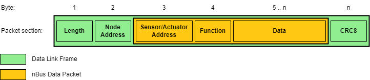
The communication is a master/slave request/response, allowing not only node addressing but also specific sensor addressing, as a communication node might consist of sensors as well as actuators. Packet structure consists of a link frame and an application packet as shown following figure.
In a single nBus network, only one master is permitted, which sends data requests, slave commands and application error handling. The information about the target service is contained in a single function byte and supports up to 128 function codes. The MSB of the function byte is reserved for an error flag.
These functions range from version information, data request, node and sensor parameter configuration to node echo, calibration, sleep and wake requests. nBus supports broadcast for the entire network (e.g. clock synchronization across nodes or calibration of all inertial sensors), broadcast for individual node elements (e.g. setting the same gain for each force sensor in a single node) and also node element uni-cast (i.e. sending data for display on an integrated display).
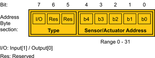
The target element is specified in the element address byte as shown on following figure. The first three bits are used to indicate the element type with the first bit's designation as an input/output selector and two reserved for later versions. The remaining bits are used for element addressing. This way we can integrate up to 31 sensors and 31 actuators into a single node.
The slave node listens to the master's requests and generates corresponding responses. The distinction between transmission types is made by node and element address bytes, as shown in following table, where X is in <1,127> and represents a node address. Y being an element address (Y is in range <1,31> for outputs, or Y is in <129,159> interval for inputs). Both slave and master nodes implement transmission error detection and correction. In the event of a transmission error, the node that detects the error sends a data packet with a set error flag and an error code as data. This code can be anything from a bad CRC result to an invalid parameter request.
| Node address | Element address | Description |
|---|---|---|
| 0 | 0 | Broadcast to all nodes and elements. |
| 0 | Y | Broadcast to specific elements |
| X | 0 | Unicast to node, single node broadcast |
| X | Y | Unicast to node element |
Supported functions
In following table, the allowed values of 4rd byte (Function) is shown.
|F | err | NP | ~R/W | CODE ||||| Function
code | Function
name|Read
operation|Write
operation|
| -- | -- | -- | -- | -- | -- | -- | -- | -- |--|--|--|--|
| bit | 7 | 6 | 5 | 4 | 3 | 2 | 1 | 0 | | | | |
| --- | --- | --- | --- | --- | --- | --- | --- | --- |---|---|---| --- |
| | | x | | 0 | 0 | 0 | 0 | 1 | x1 |ECHO |✓|-|
| | | x| | 0 | 0 | 0 | 1 | 0 | x2 |STOP | -|✓|
| | | x| | 0 | 0 | 0 | 1 | 1 | x3 |START | -|✓|
| | | x| | 0 | 0 | 1 | 0 | 0 | x4 |PARAM | ✓|✓|
| | | x| | 0 | 0 | 1 | 0 | 1 | x5 |SENSOR_CNT | ✓|-|
| | | x| | 0 | 0 | 1 | 1 | 0 | x6 |SLEEP | ✓|✓|
| | | x| | 0 | 0 | 1 | 1 | 1 | x7 |WAKEUP | ✓|✓|
| | | x| | 0 | 1 | 0 | 0 | 0 | x8 |CALIBRATE |-|✓|
| | | x| | 0 | 1 | 0 | 0 | 1 | x9 |RESET | -|✓|
| | | x| | 0 | 1 | 0 | 1 | 0 | xA |STORE | -|✓|
| | | x| | 0 | 1 | 0 | 1 | 1 | xB |DATA | ✓|✓|
| | | x| | 0 | 1 | 1 | 0 | 0 | xC |SYNC | -|✓|
| | | x| | 0 | 1 | 1 | 0 | 1 | xD |SENSOR_TYPE | ✓|-|
| | | x| | 0 | 1 | 1 | 1 | 0 | xE |INFO | ✓|-|
| | | x| | 0 | 1 | 1 | 1 | 1 | xF |... | ..|..|
command INFO
Allowed parameters. These data are hardcoded in specific apllication.
|name|description|length|example| |--|--|--|--| |NAME|name of module|8 | | |TYPE|type of module|3? | IMU,FSR,GNS| |UUID|unique ID - generated by MCU|4B |0x12345678| |HW|Hardware version|2 | 25 (meaning: 2.5)| |SW|Software version|2 | 01 (meaning: 0.1)|
Command PARAM
Sensors parameters. These data are stored in EEPROM. They can be modified.
|name|description|length|example| |--|--|--|--| |SAMPLERATE|sample rate in Hz|2 | 250 (meaning: 250 Hz)| |LOW_PASS_FILTER|low pass filter (if it is supported)| 1-2 | | |FULL_SCALE|data range|1 |int8_t range |